Open Shading Language in Blender
I’ve been playing around with Blender’s relatively new Open Shading Language support, and mmm, it’s powerful. I’m still bending my mind around shader construction, though — writing shaders is really different from writing graphics code the normal way. For example, here’s how you’d draw a circle in JavaScript on Canvas:
context.arc(x, y, radius, 0, 2 * Math.PI);
context.stroke();
But shaders don’t work that way. Instead, the shader program gets called for every pixel on the material, so you have to do something like this instead (using a distance field in this case, based on this GLSL code):
point pt = P;     // The point that gets passed in
float x = pt[0];  // OSL uses array indices for x,y
float y = pt[1];

// Get the distance from (0, 0) to the point we're processing and then
// subtract from the radius to get the distance from the circle to the point
float dist = radius - sqrt(x * x + y * y);

// If dist < 0, point is outside the circle
// If dist > border, point is inside the circle
// If dist <= border && dist > 0, point is on the circle
float t = 0;
if (dist > border) {
    t = 1;
} else if (dist > 0) {
    t = dist / border;
}

// Add the intensity control and make sure the value >= 0
float final = abs(intensity / t);

// Create the output color (and drop the red channel by half)
color c = color(final / 2, final, final);
Longer, definitely. But also much more powerful. Here’s what it looks like rendered:
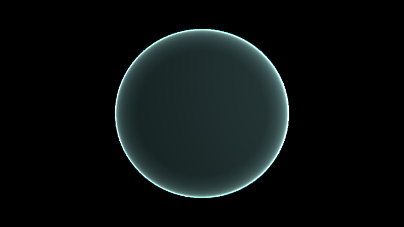
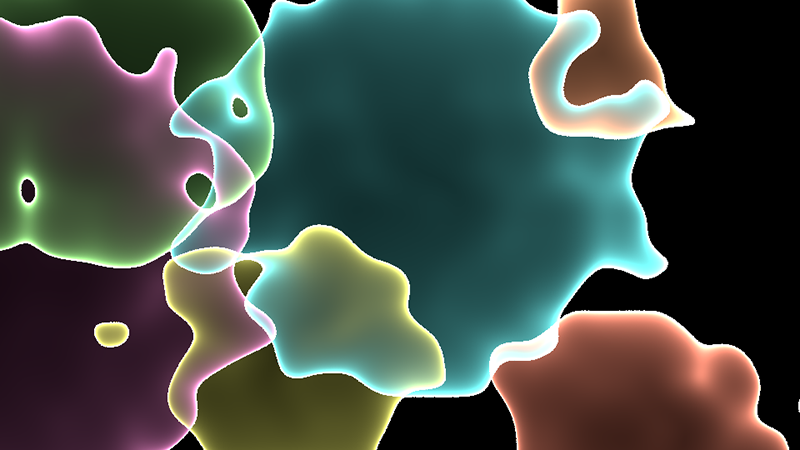
I’m not sure if doing a parametric circle like this would even be possible in Blender’s material nodes system, but with OSL it’s fairly simple (if a bit mathy) and very customizable. Add some more circles, a noise function on the distance field, and a little postprocessing and you get this:
Another example, where the OSL shader is on the box in the middle:
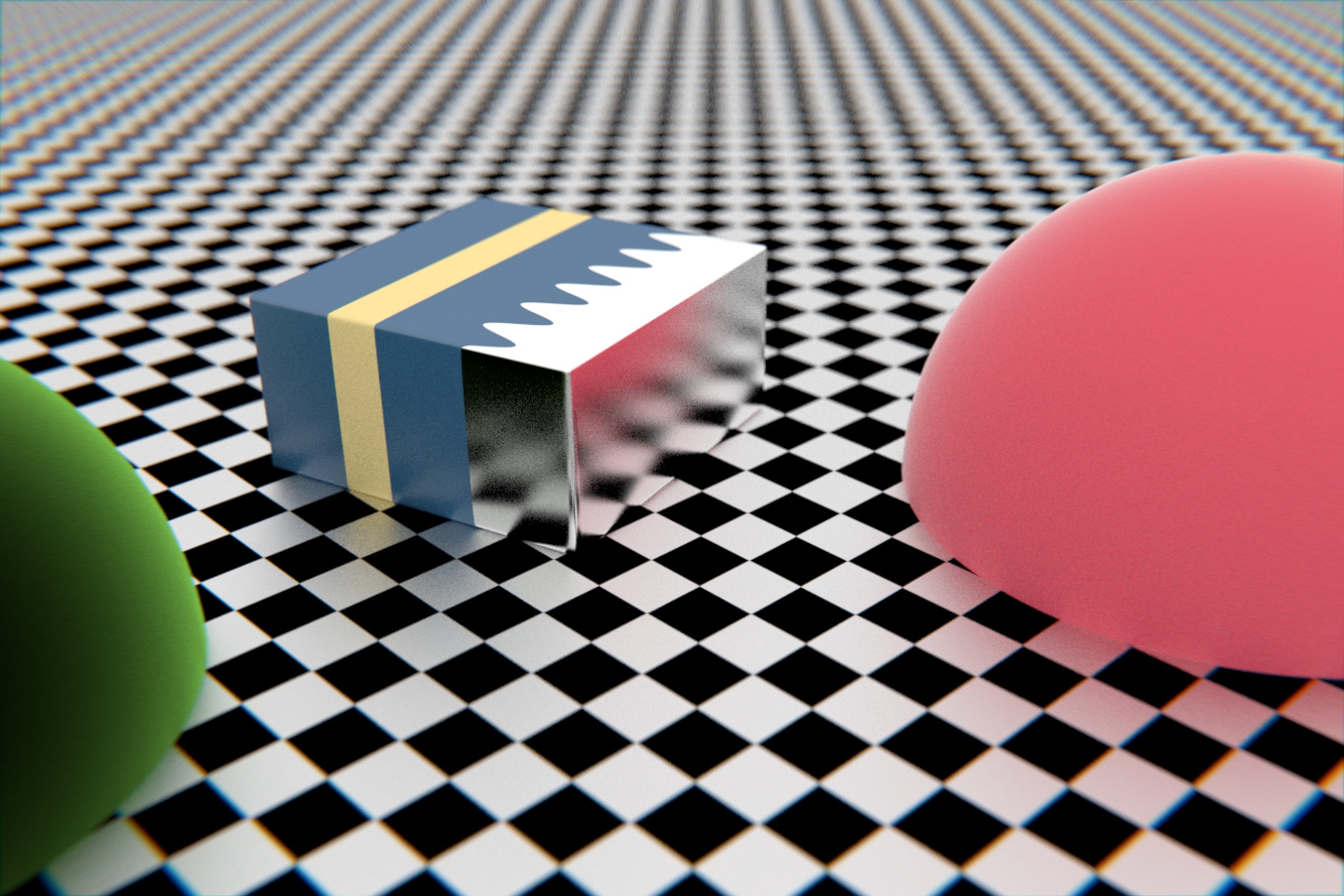
The shader looks at the x coordinate, and if it’s to the left of the divider (with a sine wave applied), it gets the blue material, and if it’s to the right, it gets the metallic material. It also adds the yellow band. Everything is exposed to the node system through parameters (inputs to the shader), so it’s easy to change values to get different looks:
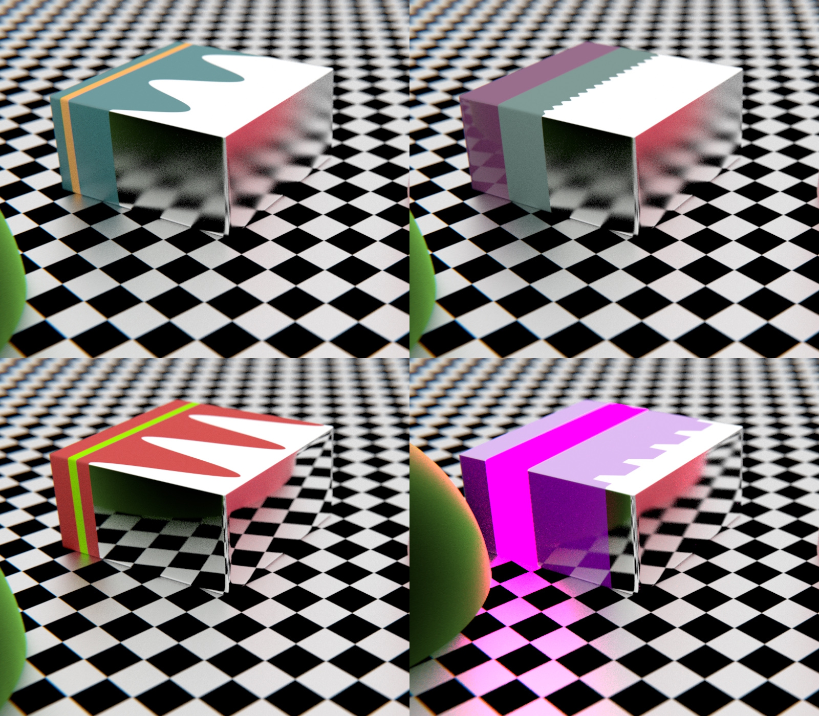
(The lower right one is a bit more of a tweak, changing the band to emit light and using a clamped abs/mod combo instead of a sine wave.)
This is all just scratching the very top layer of the surface, of course. Now I just need to brush up on my math…